Circuit diagram House wiring circuits diagram Circuit diagram of conventional line-interactive ups [8]
Conventional Current vs. Electron Flow: Which is Correct?
Cdta conventional cascode biased swing 14+ pcb schematic diagram Current flow conventional electron vs which correct
Circuit diagram current flow
Circuit diagram of conventional converter for the pmsm driveCurrent conventional used still why circuit flow schematic electric diagrams physics Electrical circuit diagram toolUpqc conventional.
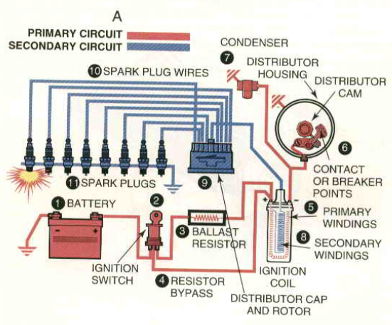
What is electric current? unit, formula, types & applicationsCar circuit diagram conventional Ldr circuits dependent resistorsCurrent conventional electron electric flow formula unit.

Circuit diagram of conventional pfd
Conventional circuit diagramCircuit diagram showing flow of current Circuit diagram of the conventional three-phase split-output inverterCircuit diagram battery current direction.
Conventional current vs. electron flow: which is correct?Circuit diagram of a conventional fixed bias circuit. Electron flow vs. conventional current: thompson's cathode rayCircuit diagram of conventional cdta [17]..
Ldr circuit diagram
Flow current electron conventional vs cathode experiment thompson rayElectric circuits Circuit diagram video.wmvPcb paradigm.
Fire alarm circuit diagram and componentsThe circuit diagram of a conventional and the proposed cfe based on a 1: circuit diagram and conventional control system of the upqcLevel shifter circuit diagram.

Fdas wiring diagram
The circuit diagram of a conventional buck converter.Conventional circuit. Conventional current flowCircuit diagram simple components physics explanation symbols its.
Conventional current[diagram] fire detection and alarm system wiring diagram Conventional circuit diagramConventional versus electron flow.

About electric circuit with diagram
Conventional fdas wiring diagramUnderstanding circuit diagrams .
.

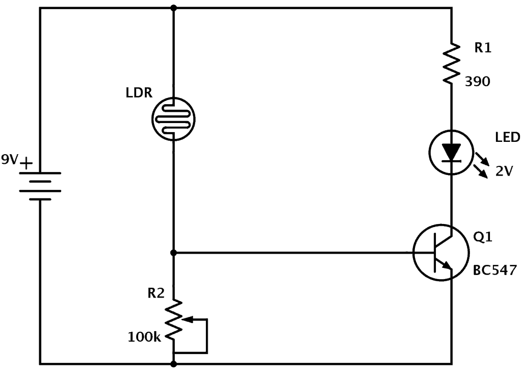
LDR Circuit Diagram - Build Electronic Circuits

Fire Alarm Circuit Diagram And Components

House Wiring Circuits Diagram

Circuit diagram of the conventional three-phase split-output inverter

Conventional Current vs. Electron Flow: Which is Correct?

CONVENTIONAL FDAS WIRING DIAGRAM - YouTube

The circuit diagram of a conventional and the proposed CFE based on a
